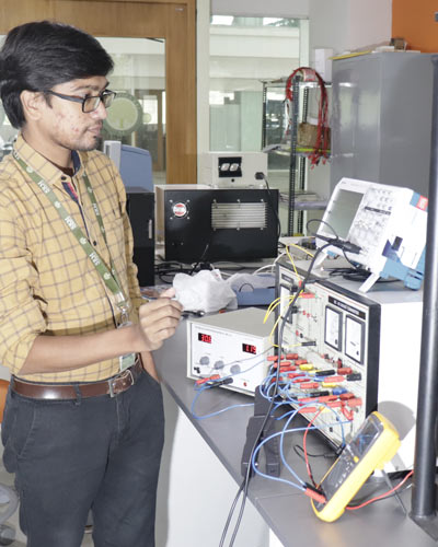
Laboratory Experiments
To verify Kirchhoff’s voltage laws.
In this experiment, the main aim is to verify Kirchhoff’s voltage Law .
Kirchhoff’s Voltage Law states that the algebraic sum of the voltages (or voltage drops) in any closed path of a network that is transverse in a single direction is zero.
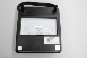
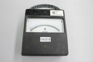
Components- Ammeter (0-10A) MC type (3)
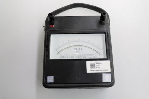
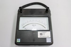
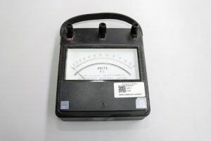
- Voltmeter (0-300V) MC Analog (1)
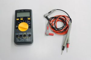
- Digital mutlimeter (1)
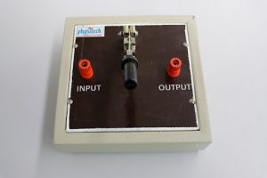
- Resistor 100 Ω (3)
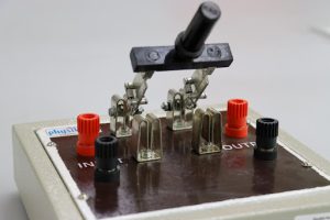
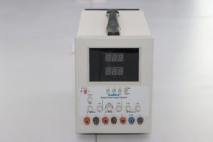
- DC Regulated power supply (0-30V)
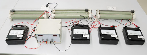
To verify Kirchhoff’s current laws.
Description
In this experiment, the main aim is to verify Kirchhoff’s current Law .
Kirchhoff’s current Law states that the algebraic sum of all the currents at any node point or a junction of a circuit is zero.
Components
- Ammeter (0-10A) MC type (3)
- Voltmeter (0-300V) MC Analog (1)
- Digital mutlimeter (1)
- Resistor 100 Ω (3)
- DC Regulated power supply (0-30V)
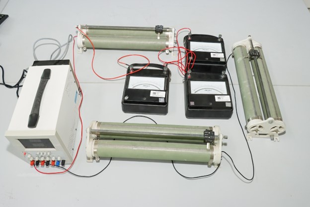
To verify Ohm's law
In this experiment, the main aim to verify Ohm’s law.
Ohm’s law states that the current through a conductor between two points is directly proportional to the voltage across the two points.
Components- Ammeter (0-10A) MC type (3)
- Voltmeter (0-300V) MC Analog (1)
- Digital mutlimeter (1)
- Resistor 100 Ω (3)
- DC Regulated power supply (0-30V)
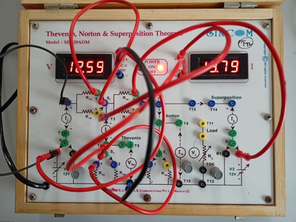
Thevenin’s, Norton’s, Superposition theorem Kit.
- To study the Thevenin’s Theorem & determine the values of VTH & RTH for the different values of Vi.
- To study the Norton’s Theorem & determine the values of Norton’s Current IN & Norton’s resistance RTH for the different values of Vi.
- To study the Superposition Theorem & determine the values of Current & Voltage across R2 for the different values of V1 & V2.
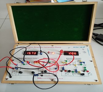
Maximum Power, Reciprocity, Superposition theorem Kit
- To study the maximum power transfer theorem & determine the value of current, voltage, source impedance & power delivered to resistive load for the differnt values of applied DC input Vi.
- To study & verify Reciprocity Theorem.
- To study & verify Superposition Theorem.
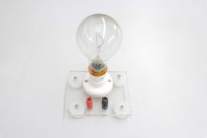
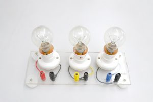
To study the V-I characteristics of an incandescent lamp.
- In this experiment, the main aim is to study and plot the following V-I Characteristics of Tungsten Filament Lamp.
- Ammeter (0-10A) MC type (1)
- Voltmeter (0-300V) MC Analog (3)
- Digital mutlimeter (1)
- Resistor 100 Ω (3)
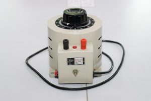
- Variac (Single phase auto transformer (1)
- Lamp holder set
- Tungsten lamp
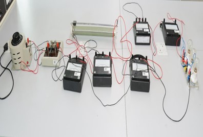
Measurement of single-phase power by using three ammeter method.
- Ammeter (0-10A) MC type (1)
- Voltmeter (0-300V) MC Analog (3)
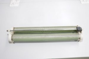
- Rheostat
- 1-phase autotransformer (1)
- Inductive load 10 Amp (1)
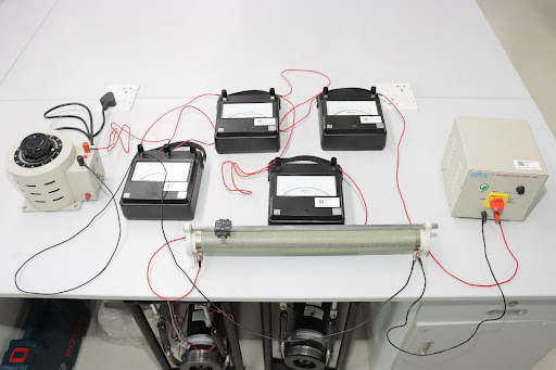
Measurement of single-phase power by using three voltmeter method.
- Ammeter (0-10A) MC type (1)
- Voltmeter (0-300V) MC Analog (3)
- Rheostat
- 1-phase autotransformer (1)
- Inductive load 10 Amp (1)
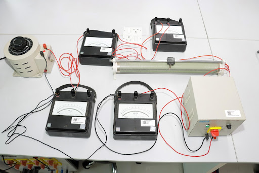
Measurement of three phase power by two-wattmeter method
- Ammeter (0-10A) MC type (1)
- Voltmeter (0-300V) MC Analog (3)
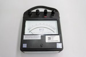
- Wattmeter (0-600)W (1)
- 3-phase autotransformer (1)
- Load rheostat 10 Amp (1)

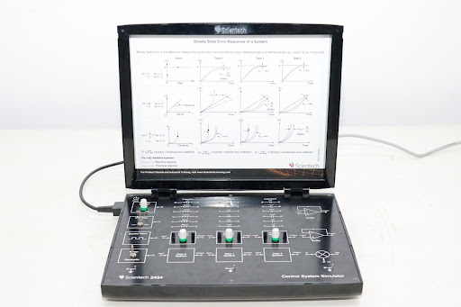
Control Systems Simulator
- Compact and user friendly learning platforms to gain invaluable knowledge about order and type of Control System.
- Square wave, Ramp wave, Parabolic wave, Unit step signal and variable DC supply are provided on board as standard inputs.
- On board Resistance, Capacitor and Inductor banks for studying different combination for the order of a system are also available.
- To observe the First/Second/Third Order control systems time response.
- To observe the Type-0/Type-1/Type-2 control systems Steady State Error (Ess) for Unit Step/Square wave/Ramp/Parabolic input.
DC Motor Position Control
- Helps the user to gain invaluable practical experience of the principles and application of DC motor position control.
- Helps in understanding the concept of Robot controls.
- To observe the position control system for different values of angular position commands.
- To observe the position control system for different values of the forward gain at different values of angular position commands.
- To observe the controller output of the system for different values of the forward gain.

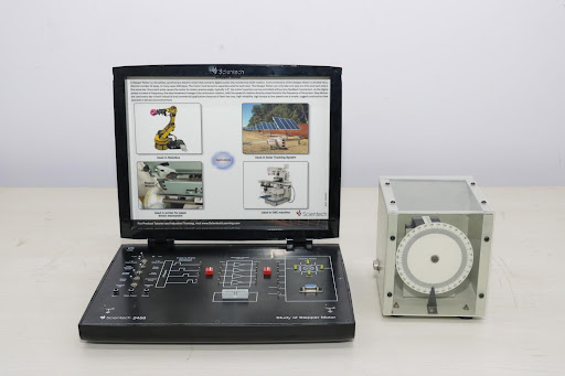
Study of Stepper Motor
- Introduce students the operation and control of stepper motor effectively.
- It helps the student in understanding half and full step angle of stepper motor with visual indication of the coil excitation process.
- It has a provision for connecting the motor with an external controller designed by students.
- Study and use of stepper motor in wobble mode.
- Study of Stepper Motor in Full/Half Step, Single/Two Phase, Free/Step Running Modes.
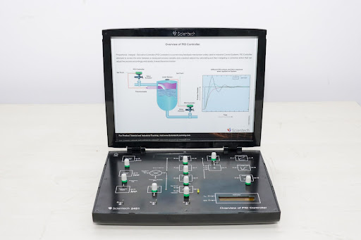
Overview of PID Controller
- Students can study two-position mode as ON/OFF Controller and continuous Controller modes as Proportional (P), Integral (I), Derivative (D), PI, PD and PID control modes.
- First order system and second order system in open loop and closed loop system.
- Study of ON/OFF control.
- Study of P, I, D controls individually.
- Study of PI, PD and PID control modes.</li/>
- Study of PID control modes for first order and second order systems.
Lead-Lag Compensation Network
- Helps the user to gain invaluable practical experience of the principles and application of Leading Lagging of a signal applied to any active network.
- Helpful to study Lead, Lag and Lag-Lead in the networks as a filter, analysis through Bode plots and compensation of the same.li>
- Study of Lead Compensator.
- Study of Lag Compensator.
- Study of Lag-Lead Compensator.</li/>

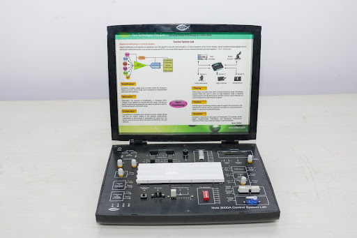
Nvis 3000A Control Systems Lab
- Exposes students to the fundamentals of Control System.
- Studies include how one device can be used manage, command, direct or regulate the behavior of other system Open Loop & Closed Loop Control.
- Nvis 3000A (as shown in below figure) has various parts like Temperature Sensor, Light Sensor, DC Motor, Servo Motor, LED lamps, IR Sensor, Relay SPST, and Relay DPDT; De-bounce switch, LED Bar, Buzzer etc. which can be used for study of Control system.
- Nvis 630 DAQ is very useful for sensing and controlling analog and digital signals of any process.
- It makes easy and interesting to interface real world signals with PC through USB bus.
- To study and observe Voltage to Frequency or Frequency to voltage conversion.
- To study and implement DC Motor Speed Control in Open Loop and Closed loop.
- To study & implement Temperature Control in Open Loop and Closed loop.
- To study & implement Light Intensity Control in Open Loop and Closed loop.
- To study & implement Servo Motor Control.
- To study & implement Home automation.
NI ELVIS III Prototyping Board
- Developed for project-based learning that combines instrumentation and embedded design with a web-driven experience to create an active learning environment in the lab.
- Delivers a greater understanding of engineering fundamentals and system design.
- Addresses engineering curriculum by integrating project-based learning, teamwork, and design with course-specific application boards and labs developed by experts from education and industry.
- Enables educators to scale to future multidisciplinary applications, driving student employability.
- Used to prototype circuits and systems across a wide variety of disciplines. It features a large central build area, convenient access to the NI ELVIS III control I/O, and integrates a set of commonly used circuit components such as buttons and LEDs to simplify prototyping.
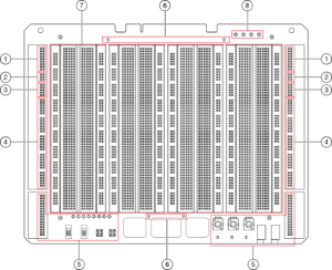
- Analog Input
- Analog Output
- Fixed User Power Supplies
- Digital I/O
- User peripherals
- Digital ground
- Central build area (breadboard)
- Fixed User Power Supplies LEDs
Quanser Mechatronic Actuators Board for NI ELVIS III
- Ideal tool to introduce a variety of common actuators and demonstrate their advantages, interfacing and operation, as well as design considerations and limitations.
- The board consists of a brushed DC motor with selectable linear and PWM amplified power amplifiers, a brushless DC motor, stepper motor, integrated servo, and modifiable LabVIEW controllers.
- The board gives the experience with working actuators, while removing the complications involved with wiring and configuring power and control circuitry. Actuator technologies are compared and contrasted, allowing users to become comfortable with making design decisions about actuators and amplifiers in real-world applications.
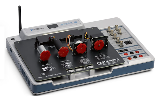 Main Features

- Brushed DC motor with 24 pulse/revolution photo microsensor
- Current sense for brushed DC motor
- Linear power amplifier
- PWM power amplifier
- Brushless DC motor with integrated Hall effect sensors
- 48 step unipolar stepper motor
- Servo motor
Quanser Controls Board for NI ELVIS III
- The Quanser Controls board is a complete platform for investigating almost all aspects of modern control theory from system modelling and PID control to stability and digital control design.
- The system consists of a deterministic DC motor with a high-resolution encoder, as well as a pendulum attachment for balance control.
 Main Features
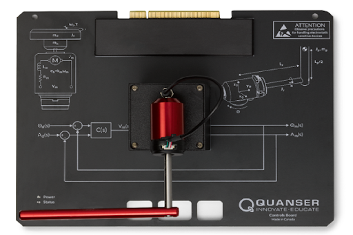
- Direct-drive brushed DC motor
- 512 count encoder mounted on the motor and on the pendulum arm
- Built in deterministic PWM amplifier mapped to theoretical motor models
- DC motor current sense
Quanser Energy Systems Board for NI ELVIS III
- The Quanser Energy Systems board is a versatile system designed to allow students to investigate and explore various sub-components of an electromechanical power system. Topic ranges from AC power generation, rectification and inversion to buck and boost DC power conversion.
- The system consists of a DC power source and three phase AC generator, three phase rectifier, switched mode power supply, inverter and transformer, DC current sink, and modifiable LabVIEW controllers.
- The board can be easily adapted to a wide range of energy system applications such as wind and solar power generation as well as consumer power supplies and electric vehicles.
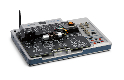
Main Features
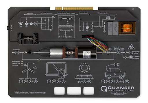
- Variable linear DC power supply
- Three-phase AC generator assembly
- Three-phase rectifier with selectable capacitance
- Buck and boost switched-mode DC power supply circuits
- Single phase inverter circuit with transformer and resistive AC load
- Adjustable DC current sink
AC TRANSMISSION LINE TRAINER
- This setup is designed to study the transmission line parameters (A,B,C,D) of a transmission line model. This set up consists of : AC transmission Line Model, meter set up.
- Measurement of Transmission line Parameters (A,B,C,D) of Short Transmission Line Model.
- Measurement of Transmission line Parameters (A,B,C,D) of Medium Transmission Line Model (T, PI& End condenser Network).
- Measurement of Transmission line Parameters (A,B,C,D) of Long Transmission Line Model.
- Study of Ferranti Effect of Transmission Line Model.
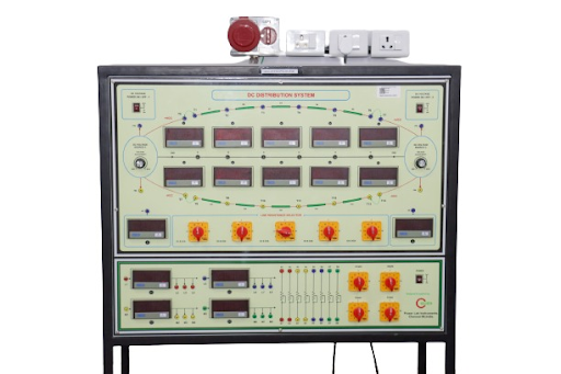
DC DISTRIBUTION TRAINER
- This Dc distribution system Trainer is specially designed to study the various type of dc distribution network system.
- Distribution system fed at one end
- Distribution system fed at both end
- Distribution system fed at centre
- Study of Ring Main Distribution network.
Study of Radial Distribution network.
Study of Inter Connected system.
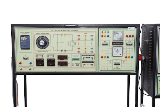
FAULT ANALYSIS OF 3 PHASE ALTERNATOR
- This set up is designed to study the measurement procedure of Sequence impedance (Positive, negative, Zero), and study the measurement of fault current by simulating various types of faults (LG,LL,LLG,LLLG etc.) under low field voltage.
- Positive Sequence Impedance
- Negative Sequence Impedance
- Zero Sequence Impedance
- Measurement of Synchronous Impedance of Alternator.
- Measurement of Fault Current for various types of faults (LG,LL,LLG,LLLG etc.).
Measurement of Sequence Impedance of Alternator.
POWER ANGLE CHARACTERISTICS OF AN ALTERNATOR
This set up is designed to study the measurement of Power angle of an alternator. This set up consists of 3 Phase Alternator with prime mover set up & Control Panel with Fault simulation switches.
ExperimentsMeasurement of POWER ANGLE characteristics of alternator with infinite bus bar.
FAULT ANALYSIS OF 3 PHASE TRANSFORMER
FAULT ANALYSIS OF 3 PHASE TRANSMISSION LINE
-
-
- Positive Sequence Impedance
- Negative Sequence Impedance
- Zero Sequence Impedance
-
CHARACTERISTICS OF SCR, TRIAC, IGBT & MOSFET
This trainer is designed to study the V-I characteristics (STATIC characteristics) of SCR, TRIAC, MOSFET and IGBT. This trainer consists one number of SCR(TYN 612), TRAIC(BTA12), MOSFET(IRF840) and IGBT(IRGBS30S) with heat sinks.
Experiments- Study of V I Characteristics of SCR.
- Study of V I Characteristics of TRAIC.
- Study of Drain and Transfer Characteristics of MOSFET.
- Study of Drain And Transfer Characteristics of IGBT.
Measurement of Sequence Impedance of transformer.

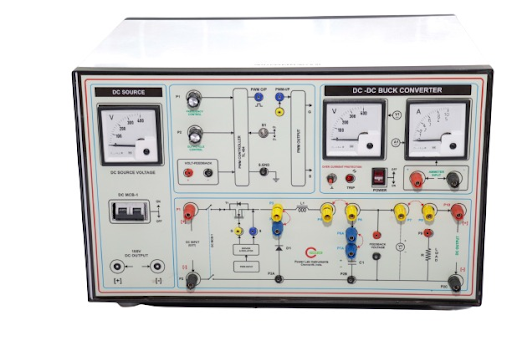
DC – DC BUCK CONVERTER
- Open Loop Control.
- Closed Loop Control
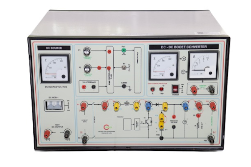
DC – DC BOOST CONVERTER
- Open Loop Control.
- Closed Loop Control
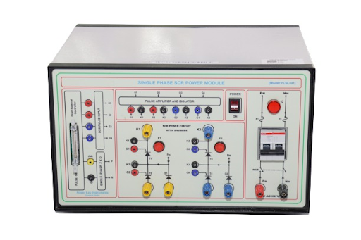
SINGLE PHASE SCR DUAL CONVERTER POWER MODULE
This module is designed to study the single phase dual converter with R, RL loads. This module is designed by using SCRs for combination of rectifier (AC to DC) and inverter (DC to AC) applications.
Experiments
Study of Single phase fully controlled full bridge converter with R & RL loads.
SINGLE PHASE & THREE PHASE PWM INVERTER MODULE
This trainer is designed to study the working of IGBT based DC-AC inverter ( single phase & 3 phase) using various PWM techniques. It consists of IGBT PWM Controller & 3 Phase IGBT Power Circuit, RL Load & DC Power supply.
Experiments- Study of uni-polar and bi-polar PWM based single –phase inverter.
- Study of single phase square PWM inverter ( Multi pulse inverter) with R load.
- Study of single phase sine PWM inverter ( SPWM inverter) with R load.
- Study of Three phase SINE PWM inverter with R load.
3 PHASE VOLTAGE SOURCE INVERTER POWER MODULE
This trainer is designed to study the working of IGBT based DC-AC inverter ( single phase & 3 phase) using various PWM techniques. It consists of IGBT PWM Controller & 3 Phase IGBT Power Circuit, RL Load & DC Power supply.
ExperimentsStudy of 3-phase PWM & non PWM Inverter.
- Study of Three phase square wave inverter (120,180 degree Mode) with R load.
- Speed control of 3 phase inverter fed induction motor based on open loop v/f control.
- Study of PMDC back to back coupled motor control.
- Study of Speed Control (Open Loop/Closed Loop) of PMDC Motor using IGBT Chopper.
- Study of Four quadrant operation of dc motor using IGBT Chopper.

SINGLE PHASE STEP DOWN CYCLO CONVERTER
This setup designed to study the working principle of single-phase step-down cyclo-converter (Mid Point type). This setup consists of Single phase cyclo converter firing circuit and SCR power circuit.
ExperimentsStudy of Single Phase step-down midpoint type cycloconverter.